 Modularrer Grabber Baukasten
Documentation
![]()
Contact: Ondrej.Hnilicka@e4t.cz
Revisions:
|
Version |
Date |
Description |
Author |
|
1.0 |
19.4.2016 |
First version |
Ondrej Hnilicka |
|
1.1 |
28.6.2016 |
Led signals,
screenshots, raw video |
Ondrej Hnilicka |
|
1.2 |
29.6.2016 |
Logs |
Ondrej Hnilicka |
|
1.3 |
29.6.2016 |
Firmwares 1.3.1-2
changed to 1.3.3-4 |
Ondrej Hnilicka |
|
1.4 |
15.9.2016 |
Added LVDS FPD Link 2
& 3 pinouts |
Ondrej Hnilicka |
|
1.5 |
1.12.2016 |
Added many things with
fw 1.5.0 |
Ondrej Hnilicka |
|
1.6 |
9.12.2016 |
Aperiodic screenshot
behaviour in 5.1 |
Ondrej Hnilicka |
|
1.7 |
29.3.2017 |
Firmware 1.5.1 + sync.
generator |
Ondrej Hnilicka |
|
1.8 |
23.1.2018 |
Screenshots, triggers,
etc. |
Tomas Tvaroha |
|
1.9 |
24.1.2018 |
Revision to 1.7.0
firmware |
Ondrej Hnilicka |
|
1.10 |
14.3.2018 |
Firmware 1.9, added:
Configuration reset, Firmware downgrading. |
Ondrej Hnilicka |
1
Table
of content
5.1.1 Storing periodical screenshots to SD card or MGB RAM
disk and accessing via Samba share
5.1.2 Accessing periodical screenshots via HTTP server
5.1.3 Streaming screenshots via TCP protocol
5.2.1 Storing triggered screenshots to SD card
5.2.2 Streaming triggered screenshots via TCP protocol
5.3 Streaming screenshots via TCP protocol
7 On/Off button and LED signals
9.1 MIB1 (STD, HIGH) and MIB2 (STD, HIGH, HIGH 9,2“):
11.2.2 Internal synchronization generator
12 Backchannel communication sniffers
2
MGB
introduction
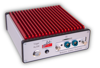 Modularrer Grabber Baukasten (MGB)
is an electronic device developed for grabbing video from VW concern displays
(ZR, ABT, FPK, etc.). It was developed by e4t – Electronics for Transportation
company in cooperation with AUDI, Volkswagen and Skoda. MGB connects directly
to video bus between video source (ZR) and video sink (display). It grabs video
data, compresses and sends them to PC via 1 Gbit ethernet. It is able to save
screenshots and record a video to SD card or USB device.
Modularrer Grabber Baukasten (MGB)
is an electronic device developed for grabbing video from VW concern displays
(ZR, ABT, FPK, etc.). It was developed by e4t – Electronics for Transportation
company in cooperation with AUDI, Volkswagen and Skoda. MGB connects directly
to video bus between video source (ZR) and video sink (display). It grabs video
data, compresses and sends them to PC via 1 Gbit ethernet. It is able to save
screenshots and record a video to SD card or USB device.
![]()
![]()
![]()
![]()
MGB can stream its video in different formats. Lossy
codecs are H264 and Motion JPEG. Lossless option is raw video. Screenshots are
stored in lossless space-saving PNG format.
MGB user can select an Area of Interest (rectangle of
video) which is cut-out from the video stream and streamed separately to PC.
This capability is convenient for space savings and framerate acceleration.
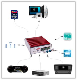
Current available interfaces are
·
LVDS FPD Link 2
·
LVDS FPD Link 3 (UB948)
These
interfaces are capable of grabbing all LVDS systems used in VW concern.
Input video signal parameters
(resolution, signal active level) are detected automatically and user does not
need to set them manually. In some cases is necesarry to set proper link settings
(single or dual) according to video interface type.
MGB has a trigger functionality. A trigger caused by
two external inputs, CAN bus or trigger button is arbitrarily set to control
MGB startup, screenshots or video record.
AUDI implemented a VW IP library for MGB integration to
test automation.
 Settings of MGB’s parameters is
done easily with web-interface based configurator. User can define network
parameters, video codec, Area of Interest or screenshot period.
Settings of MGB’s parameters is
done easily with web-interface based configurator. User can define network
parameters, video codec, Area of Interest or screenshot period.
The MGB software can be easily updated by customer (SD
card).
Technical specifications:
|
Interface |
LVDS FPD Link 2, 3 |
|
Video |
H264,
MJPEG, RAW |
|
Screenshot |
PNG, RAW |
|
Network |
1
Gbit/s - TCP, UDP |
|
Connection |
CAN, UART, I2C, 2x input, 1x output, HDMI
(since pcb version 3) |
|
Power
supply |
9
V to 30 V |
|
Temperature |
0°C to 70 °C |
|
Dimensions |
17
x 17 x 6 cm |
3
Starting tutorial
Here is a
step by step description how to start with MGB.
1) Set your PC network card to the IP
address 192.168.1.1 and network mask
to 255.255.255.0
2) Connect MGB to your PC with an
Ethernet cable
3) Start an internet browser and type “192.168.1.200” to its address field (default MGB IP address)
4) MGB’s web interface should appear.
There is an IP settings, video settings and so on
5) Connect MGB’s video input to your
video source (ZR, ABT, FPK). The video source must be switched off. Video
cables are described in the section Connection
cables
6) Connect MGB’s power cable. MGB
starts booting (cca 20 s) and then waits for a video source signal
7) Turn on the video source (ZR, ABT,
FPK). If you have a LVDS FPD Link interface module, the LED on the module
should switch on (LVDS signal locked)
8) Start a video software and set it to
the MGB stream. It is explained in Video software
section of this manual.
4
Video
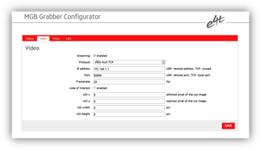
MGB is
capable of streaming video. To make use of this feature, enable it by checking
the appropriate checkbox in web interface (Video -> Video).
4.1
Encoding
Video
can be encoded by various codecs and streamed by various transport layers, all
this is configurable in web interface (Video -> Protocol). Supported
options:
·
H264-RTP-UDP video encoded by H264 codec,
packetized by RTP protocol and transferred by UDP protocol. The destination URL
is configured in web interface (Video -> IP address / Port). Maximal
resolution is 1920x1080.
·
H264-MPEGTS-TCP video encoded by H264 codec,
multiplexed to MPEGTS stream and transferred by TCP protocol. MGB acts as
server, whose listening port is configured in web interface (Video -> Port).
Maximal resolution is 1920x1080.
·
JPEG-RTP-UDP each frame is encoded by JPEG
method, packetized by RTP protocol and transferred by UDP protocol. The
destination URL is configured in web interface (Video -> IP address / Port).
Maximal resolution is 1920x1080.
·
JPEG-MUX-TCP each frame is encoded by JPEG
method, multiplexed and transferred by TCP protocol. MGB acts as server, whose
listening port is configured in web interface (Video -> Port). Maximal
resolution is greater than 1920x1080 (2820x720 is possible).
·
RAW-RTP-UDP raw video frames (YUV 4:2:0) are
packetized by RTP protocol and transferred by UDP protocol. The destination URL
is configured in web interface (Video -> IP address / Port). Maximal
resolution currently not known.
·
RAW-TCP raw video frames (YUV 4:2:0) are transferred
by TCP protocol. MGB acts as server, whose listening port is configured in web
interface (Video -> Port). Maximal resolution is greater than 1920x1080 (2820x720
is possible).
The
actual video format information is available via Samba share at URL \\<mgb‑ip>\ramfs\videofmt.txt and via
HTTP protocol at URL http://<mgb‑ip>/videofmt.txt.
The content of videofmt.txt file
consists of these pure text lines:
<width
of video frame in pixels>
<height
of video frame in pixels>
<fourcc
(encoded as hexadecimal number prefixed by 0x)>
<Protocol
selected in web interface (Video -> Protocol)>
The videofmt.txt file is guaranteed to be
available only when MGB is streaming.
It is
important to note, that for all the above options the underlying colour
encoding is YUV 4:2:0. Currently the original colour encoding at LVDS FPD Link
is RGB, so it is internally transcoded.
4.2
Area
of interest
MGB is
capable to stream only specific area of the original full-frame area. To make
use of this feature, enable it by checking the appropriate checkbox in web
interface (Video -> Area of interest). Then set the specific area of
interest parameters to some valid values.
·
AOI x - horizontal coordinate of AOI top-left
corner, in pixels
·
AOI y - vertical coordinate of AOI top-left corner,
in pixels
·
AOI width - AOI width, in pixels
·
AOI height- AOI height, in pixels
Note,
that the values must represent valid configuration. It means, that selected
area of interest must be nonempty subset of the original full-frame area. In
case of any invalid configuration full-frame video will be streamed.
4.3
HDMI
preview
When
enabled in web interface (Video -> HDMI output), then video preview is
available on HDMI interface (note that it can slow down the LAN video framerate
because it utilizes the same CPU).
4.4
Triggered video recording
MGB is
capable of recording video stream triggered by some user defined event. These
so called triggered video streams are stored to SD card. To get more
information about trigger events see chapter Triggers.
Triggered
video streams are stored into video
folder of the SD card. The video filenames are constructed in this way:
mgb_<YYYY-MM-DD_HH-MM-SS>.<suffix>
where <YYYY-MM-DD_HH-MM-SS> represents screenshot timestamp:
YYYY – year,
MM – month, DD – day, HH – hour, MM – minutes, SS – seconds
The
video stream encoding is determined by setting in web interface (Video ->
Protocol). Video recording feature is available only for these options:
·
H264-RTP-UDP video encoded by H264 codec, stored
in MTS container (suffix .mts)
·
H264-MPEGTS-TCP video encoded by H264 codec, stored
in MTS container (suffix .mts)
·
JPEG-RTP-UDP video encoded by MJPEG codec,
stored in MKV container (suffix .mkv)
·
JPEG-MUX-TCP video encoded by MJPEG codec,
stored in MKV container (suffix .mkv)
Currently
there are some issues when recording stream encoded by MJPEG, so we don’t
recommend to use recording feature in this case.
For
purpose of having some part of video stream, that precedes the trigger event,
the video stream is steadily buffered. The size of this pre-trigger buffer is
configured in web interface (Video -> Pre-trigger buffer). The supported
buffer size ranges between 0 and 60 seconds.
For
purpose of having exactly marked the time of trigger event, a small “T”
character mark is inserted into video stream. It is inserted to the top-left
part of the video frame and it is visible for 3 seconds. To make use of this
trigger-mark feature enable appropriate checkbox in web interface (Video ->
Trigger mark).
During
video recording the leaving disk free space is checked each 10 seconds. When
the free space falls below 100MB, recording is stopped automatically.
Active
video recording is signalized by fast yellow flashing. Start of recording has
very quick response, but when stopping recording, MGB has to copy all the
buffered data to SD card and properly close the container file. This can take
several seconds (when yellow light still flashes – and it seems it did not get
the signal). Please be patient.
5
Screenshots
5.1
Periodical
screenshots
MGB is
capable of taking periodical screenshots. They can be stored to SD card or MGB
RAM disk and at these locations accessed via Samba share or HTTP server. Since
version 1.5.0. MGB is able to directly stream screenshots via TCP protocol.
5.1.1
Storing
periodical screenshots to SD card or MGB RAM
disk and accessing via Samba share
If
enabled in web interface (Photo -> Periodic screenshots), MGB takes
periodical screenshots. These screenshots are stored to filesystem. Since version
1.5.0 it must be enabled in web interface (Photo -> Store to filesystem). If
an SD card is inserted, these screenshots are stored to the SD card. If SD card
is not inserted, screenshots are stored to the internal MGB RAM disk.
Internally this is achieved by mounting SD card device (when inserted) over MGB
RAM disk. MGB RAM disk is much faster than SD card, but also it is a volatile
memory, so screenshots are lost when MGB shutdowns. Either SD card or RAM disk
are accessible via Samba share at the same path \\<mgb‑ip>\sdcard\periodic_screenshots.
When SD
card is inserted, periodic_screenshots folder accesses data on SD card,
when SD card is removed, periodic_screenshots folder access data on MGB RAM disk.
We do
not recommend to use SD card as a screenshot storage for long term tests with
low screenshot period (e.g.: test-automation weekend tests with period less
than 1s).
Period,
format and maximum number of screenshots can be configured in web interface
(Photo -> Period, Photo -> Format, Photo -> Max stored frames).
There
are two possible formats the screenshots will be encoded with, PNG and RAW.
When RAW is selected, the screenshot consists of header and image data. Header
(4 bytes) consists of width (uint16) and height (uint16), represented in
little-endian order. Image data consists of pure sequence of RGB data, where
each colour takes one byte (uint8). So the byte order of RAW screenshot looks
like this: WWHHRGBRGBRGBRGB….. etc.
Storing
of screenshots uses concept of steadily overflowing filesystem ring-buffer. The
size of this buffer is determined by web interface option “Max stored frames”.
The screenshot filenames are constructed in this way:
mgb<cnt>.[png|raw]
where
<cnt> represents screenshot counter, consisting of 10 decimal digits. The
first taken screenshot encoded in PNG is stored into file of this name:
mgb0000000000.png
When the
number of screenshots reaches the configured maximum, overflow occurs and it is
processed in such way the oldest screenshot is deleted and then the new one is
stored. The counter is not affected by this overflow and it still counts-up.
There is
another Samba shared path, namely \\<mgb‑ip>\ramfs\screenshot. This path is actually a link to
the most recently stored periodical screenshot.
5.1.2
Accessing
periodical screenshots via HTTP server
Another
way to access the screenshots is via MGB’s HTTP server at URL http://<mgb‑ip>/screenshot
This URL is actually a link to the most recently stored periodical screenshot.
To make use of this access, enable both “Periodic screenshots” and “Store to
filesystem” options in web interface.
5.1.3
Streaming
screenshots via TCP protocol
See chapter
Streaming screenshots via TCP protocol
5.2
Triggered
screenshots
MGB is
capable of taking screenshots upon some user defined trigger events. These so
called triggered screenshots can be stored to SD card and since version 1.5.0. they
can be directly streamed via TCP protocol. To get more information about
trigger events see chapter Triggers.
5.2.1
Storing triggered screenshots to SD
card
Triggered
screenshots are stored into screenshots
folder of the SD card. The screenshot filenames are constructed in this way:
mgb_<YYYY-MM-DD_HH-MM-SS-MMM>.[png|raw]
where <YYYY-MM-DD_HH-MM-SS-MMM> represents screenshot timestamp:
YYYY –
year, MM – month, DD – day, HH – hour, MM – minutes, SS – seconds, MMM –
milliseconds
The
screenshot file format is determined by setting in web interface (Photo ->
Format).
5.2.2
Streaming triggered screenshots via
TCP protocol
See chapter
Streaming screenshots via TCP protocol
5.3
Streaming screenshots via TCP
protocol
Since
version 1.5.0. MGB is able to directly stream periodical screenshots via TCP
protocol.
Since
version 1.6.0. MGB is able to directly stream triggered screenshots via TCP
protocol.
TCP
server is listening on port, whose value can be configured in web interface
(Photo -> Server port). Screenshots are always streamed in raw format
(agnostic to option Photo -> Format) and it is the same format as used to
store raw screenshots to SD card.
The
screenshot consists of header and image data. Header (4 bytes) consists of
width (uint16) and height (uint16), represented in little-endian order. Image
data consists of pure sequence of RGB data, where each colour takes one byte
(uint8). So the byte order of RAW screenshot looks like this: WWHHRGBRGBRGBRGB…..
etc.
If
periodical screenshots are enabled in web interface (Photo -> Periodic
screenshots), MGB can stream the screenshots to all connected TCP clients. Each
client can individually enable or disable streaming of these periodical screenshots.
Remember, that mentioned web interface option acts as master. When TCP client
wants to receive the periodical screenshots, it has to be enabled both in web
interface and at TCP socket level. By default (because of backward
compatibility) at TCP socket level the streaming of periodical screenshots is
enabled. Scroll below to see the commands.
Whenever
appropriate trigger event occurs, MGB streams the triggered screenshot to all
connected TCP clients. There is no possibility to enable or disable the streaming
at TCP socket level.
Moreover,
each TCP client has the possibility to individually request a screenshot. Such
a screenshot is streamed only to the requesting TCP client. Scroll below to see
the commands.
Currently
only these simple one-byte commands can be issued by the TCP clients:
0x01 –
request screenshot
0x02 –
enable streaming of periodical screenshots
0x03 –
disable streaming of periodical screenshots
6
Triggers
MGB is
capable of performing some actions upon some events. Triggering events and
responding actions can be configured in web interface (Triggers).
6.1
Responding
actions
·
SCREENSHOT-TO-TCP sends screenshot to all connected
TCP clients. See Streaming triggered
screenshots via TCP protocol .
·
SCREENSHOT-TO-SDC stores screenshot to SD card. See Storing triggered screenshots to SD card.
·
VIDEOREC-START starts video recording. See Triggered video recording.
·
VIDEOREC-STOP stops video recording. See Triggered video recording.
·
VIDEOREC-TOGGLE toggles video recording. See Triggered video recording.
·
MGB-ON switch-on MGB
·
MGB-OFF switch-off MGB
6.2 Triggering events
Trigger button
release
This event fires when MGB’s main/power button is released. Note, that the preceding pushed state may not last for too long time, because long push causes switching MGB off.
External triggers TR1 and TR2
These
ones are the hardware pins located at the back side of MGB box. Rising or
falling levels at these pins can be configured as triggering events. These
trigger inputs can be used two ways:
1)
Keep
„TRx 3.3V“ DIP switch on rear side of MGB off. This means that trigger input
has zero voltage and to rise a trigger it must be connected to any external
voltage source (in range of 3.3V – 20V). Note that MGB has galvanically
isolated power source. For this reason GND on trigger connector must be
connected to trigger power source ground.
2)
Set
„TRx 3.3V“ DIP switch to ON state. This connects the trigger input via pull-up
resistor of 3.3 kohm to 3.3 V of MGB internal power supply. This allow
user just to trigger by shorting TR input with GND on the trigger connector (or
use a relay box). We recommend to use these pull-ups and a relay box to avoid
potential ground loops caused by connecting MGB trigger ground with a ground of
a trigger power supply.
CAN matches 1 and
2
These events fire when configured CAN matches occur. The match occurs only when this expression evaluates to true:
(ID == id) && ((DATA
& mask) == (data & mask))
|
ID |
- |
received CAN message identifier |
|
DATA |
- |
received CAN message data |
|
id |
- |
configured CAN message identifier (Triggers -> Identifier) |
|
data |
- |
configured CAN message data (Triggers -> Data) |
|
mask |
- |
configured CAN message data mask (Triggers -> Data mask) |
CAN timeout
This vent. fires when no CAN message is received within configured time interval (Trigger -> Timeout). This also means, that the CAN interface turns into sleep state.
CAN wakeup
This vent. fires whenever CAN interface is in sleep state and any CAN message is received. This also means, that the CAN interface turns into awake state.
MGB startup
This vent. fires when MGB startup sequence finishes and MGB gets running.
7
On/Off button and LED signals
To
switch MGB on, short press On/Off button (< 500 ms)
To
switch MGB off, long press On/Off button (> 3000 ms). It works cca 20 sec
after proper startup.
Led
signalling was changed in firmware 1.3.0
Current led
signals (firmwares since 1.3.1)
|
LED signal |
Meaning |
|
Green flashing |
Starting |
|
Green light |
Running |
|
Blue light |
Video streaming |
|
Yellow flashing |
Video recording (since firmware 1.6.6) |
|
Pink flash |
Screenshot taken (since firmware 1.6.6) |
|
Pink light |
Taking screenshots at high frequency (store to filesystem disabled) |
|
Red flashing |
Shutting down |
|
Orange flashing |
Firmware download |
|
Red light |
Error (download logs and restart MGB) |
Old led
signals (firmwares up to 1.2.6)
|
LED signal |
Meaning |
|
Change colour |
Normal operation |
|
Green flashing |
Shutdown |
|
Orange flashing |
Firmware download |
8
Firmware update
! Note that since firmware 1.9, downgrading to
1.7.0 and older versions need a special manual intervention described here.
New
firmware download procedure is descbed here:
1)
Unzip
a firmware file to your PC
2)
Erase
some SD card (at least 1 GB)
3)
Copy
the content of the “SD” folder to the SD card
4)
Turn
off MGB and disconnect it from power supply
5)
Insert
the SD card
6)
Press
and hold MGB’s On/Off button and connect a power supply at the same time
7)
MGB’s
LED starts flashing orange, release the On/Off button
8)
Now
is MGB downloading its firmware. Do not release the SD card, do not disconnect
its power supply. The whole process should take up to 5 minutes. Then the MGB
starts up with a new firmware.
*) If
orange LED flashes more than 5 mins or red LED light, disconnect the MGB from
power supply and try it again from point 4.
8.1 Firmware downgrading
At firmware
version 1.9, the flashing sequence was slightly changed. Upgrading from older
FWs to 1.9 and later works as before, but downgrading from firmware 1.9 and
later to 1.7.0 and former needs the following steps to be done:
1)
Erase
some SD card (at least 1 GB)
2)
Copy
the content of the “SD” folder to the SD card
3)
Turn
off MGB and disconnect it from power supply
4)
Insert
the SD card
5)
Press
and hold MGB’s On/Off button and connect a power supply at the same time
6)
MGB’s
LED starts flashing orange, release the On/Off button
7)
Now
is MGB downloading its firmware. Do not release the SD card, do not disconnect
its power supply. Wait 3 mins or check MGB console output on rear side UART
connector. MGB still flashes orange and should be booted to Angstrom linux.
8)
Unplug
power cable of the MGB, wait 10sec and plug it again. MGB is flashing green and
booting.
9)
Connect
to MGB console via UART (rear connector of the MGB box) or via putty
(Ethernet).
10)
Write
the following commands:
·
root
·
cd
MGB
·
./MGB_tools
11)
MGB
starts flashing FPGA and power management mcu (lpc). It can take 2 minutes.
12)
Restart
MGB, the older firmware is properly flashed.
9
Connection
cables
MGB is
delivered without connection cables because of a variety of video systems. Here
in this section described known cables and their ordering documents are
described.
9.1
MIB1
(STD, HIGH) and MIB2 (STD, HIGH, HIGH 9,2“):
1) Connection cable between ZR and MGB
is described in this document. This cable
is ordinary delivered together with the ZR.
2) Connection cable between MGB and ABT
is described here.
9.2
MIB2+:
1) Connection cable between ZR and MGB
is described in this document.
2) Connection cable between MGB and TOP
display (radio display) is described here.
3) Connection cable between TOP display
and MGB is described here (the same as
1)*
4) Connection cable between MGB and BOT
display (clima display) is described here
(the same as 2)*.
9.3
MIB2+
ICL:
1) Connection cable between ZR and MGB
is described in this document.
2) Connection cable between MGB and ICL
is the same one (described in this document).
Cables can
be ordered from: MD ELEKTRONIK GmbH, Neutraublinger Str. 4, D 84478
Waldkraiburg, Deutschland.
10
Video
software
An
ordinary IP camera viewer could be used for MGB video visualisation. Here the
VLC (VideoLAN) player is described.
VLC can
be downloaded here. When MGB is
turned on and streaming, its video is shown according to the “Protocol” set in
web interface.
H264-RTP-UDP:
execute this sdp file. The file is set to
MGB IP 192.168.1.200 and port 50000 and must be set according to right values.
JPEG-RTP-UDP:
execute this sdp file. The file is set to
MGB IP 192.168.1.200 and port 50000 and must be set according to right values.
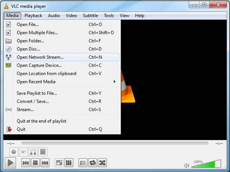
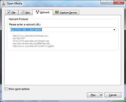
H264-MPEGTS-TCP
and JPEG-MUX-TCP: in VLC choose “media” and “Open Network Stream”. Then set a
network URL to: tcp://192.168.1.200:50000
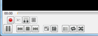
Taking a
snapshot and recording video in VLC
Select “Advanced
Controls” under a “View” menu. Record and Snapshot buttons will appear. Taking
a snapshot saves a .png picture at c:\Users\<user
id>\Pictures. Recording stores a video to c:\Users\<user id>\Videos.
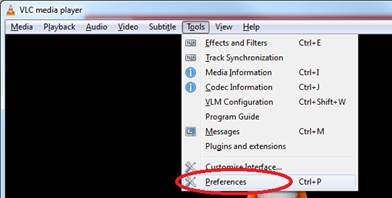
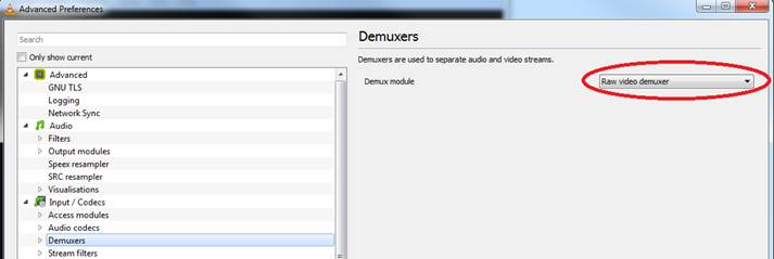
For RAW video stream is necessary to set
video parameters at VLC Demuxer video settings:
1)
Tools\Preferences
2)
Click
“All” down at the “Show settings”
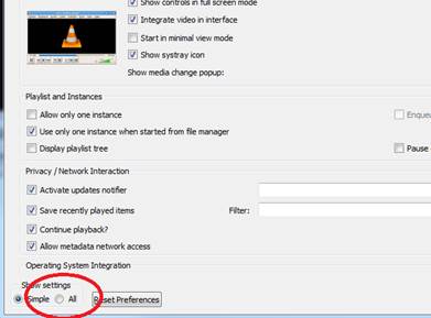
3)
At
“Demuxers” menu choose “Raw video demuxer”
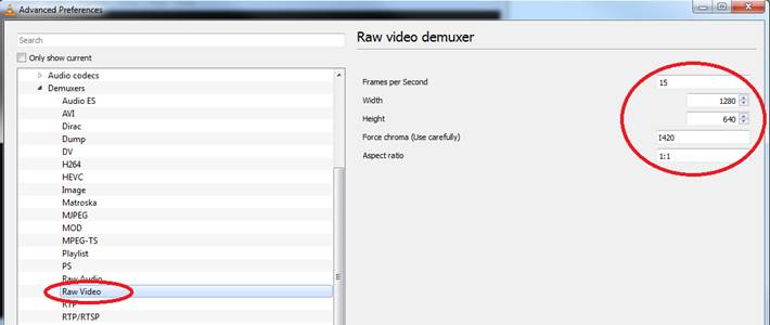
4)
Then
set the parameters according to the ZR video size or use MGB detected
parameters stored in \\mgb-ip\ramfs\videofmt.txt
Framerate set between 1 to 20
Width set to width of the ZR display (the value
must be divisible by 16 – round up to the next divisible by 16)
Height set to height of the ZR display (the
value must be divisible by 16 – round up to the next divisible by 16)
Force chroma set to “I420”
Ascpect ratio set to “1:1”
5)
Press
“Save” and show stream via Media/Open Network Stream with tcp://192.168.1.200:50000 (similar to H264-MPEGTS-TCP).
11
Interface modules
MGB has
commutable interface that allows future development of new modules for new
video interfaces.
Since
firmware version 1.5.0, the module must be selected at web interface in the
“Interface/Module” option. After changing this value, MGB should be restarted. Interface modules must be changed in MGB power off state.
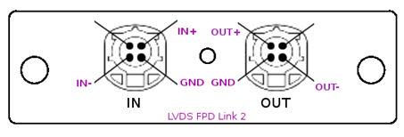
11.1
LVDS
FPD Link 2 module:
Consists of
DS90UR916 deserializer. It is capable of grabbing all LVDS FPD Link 2 systems.
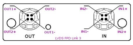
11.2
LVDS
FPD Link 3 module:
Consists of
DS90UB948 deserializer. It is capable of grabbing all LVDS FPD Link 3 systems.
11.2.1
Custom
configuration
FPD Link
3 protocol is more complex than FPD Link 2. For this reason, FPD Link 3
settings require much effort to fit in a given system. Unfortunately we found
that no universal settings exist and the settings changes time to time.
Therefore we implemented a special FPD Link 3 options in web interface that set
serializer and deserializer registers by custom values. Also serializer and
deserializer resets are set via web interface and could be set according to a
system needs.
A few
known configurations are in text below. These values was found experimentally
and could be changed occasionally in the future.
MIB2+
MGB between ZR and TOP display:
LVDS input: DUAL (since version 1.6.0)
OpenLDI: DUAL (since version 1.6.0)
On Lock falling edge reset – DES-SER
On lock rising edge reset – DES-SER
Custom configuration – disabled
Internal HSYNC/VSYNC generator - disabled
MIB2+
MGB between TOP and BOT display:
LVDS input: DUAL (since version 1.6.0) – one SW version of D5 used SINGLE
OpenLDI: DUAL (since version 1.6.0) – one SW version of D5 used SINGLE
On Lock falling edge reset – DES-SER
On lock rising edge reset – DES-SER
Custom configuration – disabled
Internal Hsync/Vsync generator – enabled (this can vary according to D5 SW
version)
DE/Vsync length – 1000
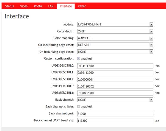
MIB2+
ICL (MGB firmware prior 1.7.0):
On Lock falling edge reset – DES-SER
On lock rising edge reset – NONE
Internal HSYNC/VSYNC generator - disabled
Custom configuration – enabled
LVDS3DESCTRL0 – 0x041EF800
LVDS3DESCTRL1 – 0x30113000
LVDS3DESCTRL2 – 0x00000001
LVDS3SERCTRL0 – 0x001E00D2
LVDS3SERCTRL1 – 0x00802000
Internal HSYNC/VSYNC generator – disabled
MIB2+
ICL (MGB firmware since 1.7.0):
LVDS input: DUAL
OpenLDI: DUAL
On Lock falling edge reset – DES-SER
On lock rising edge reset – NONE
Internal HSYNC/VSYNC generator - disabled
Custom configuration – disabled
Internal HSYNC/VSYNC generator – disabled
Back channel - UART
Back channel sniffer - enabled
MIB2
HIGH 9,2”:
On Lock falling edge reset – NONE
On lock rising edge reset – NONE
Custom configuration – disabled
Internal HSYNC/VSYNC generator –
disabled
MIB3 OI
9,2”:
Internal HSYNC/VSYNC generator -
disabled
Custom configuration – enabled
LVDS3DESCTRL0: 0x049EB800
LVDS3DESCTRL1: 0x00003440
LVDS3DESCTRL2: 0x00000001
LVDS3SERCTRL0: 0x001E00D2
LVDS3SERCTRL1: 0x00802000
* Note that firmware 1.7.0 has a bug which causes black output in this
configuration. Use a later firmware instead.
ICAS3
iID:
LVDS input: SINGLE
OpenLDI: SINGLE
Custom configuration – disabled
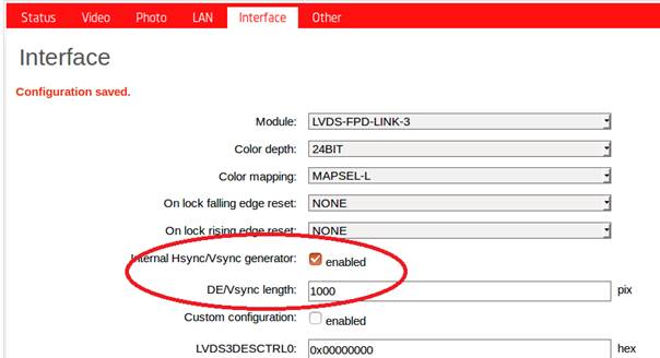
11.2.2
Internal
synchronization generator
Internal
synchronization generator (first released in firmware 1.5.1) generates internal
VSYNC (Vertical Synchronization) pulses according to DE (Data Enable) signal.
It must be enabled in systems which lack these signals e.g. MIB2+ Bottom
display. On the other hand this feature should be disabled if video contains
these signals. “DE/Vsync length” sets the size of the DE gap that generates the
VSYNC pulse e.g.: if set to 1000 and DE is active high, low level on DE longer
than 1000 pixels triggers the VSYNC pulse. This value should be set longer than
DE gap at the end of the line and shorter than DE gap at the end of the frame.
12
Backchannel
communication sniffers
LVDS FPD
Link 3 interface has a special bidirectional data channel called Backchannel.
This Backchannel is in some systems used to transfer a special data at a
special protocol.
In MGB,
UART and SPI Backchannel sniffers were implemented. These sniffers allows user
to listen the communication of Backchannel UART or SPI by forwarding its data
to a TCP port.
Three
communication scenarios exists. UART, SPI Forward channel, SPI Reverse channel.
First user must set properly which communication scenario MGB is connected to.
If user set scenario badly or not, the communication between ZR and peripheral
is broken (MGB does not resending data correctly through FPD Link channel).
Settings of backchannel communication can be done in “Interface” menu.
“Backchannel” here sets the type of scenario (communication protocol). “Back
channel sniffer” enables the forwarding of data to “Back channel port” and
“Back channel UART baudrate” is valid for UART scenario only.
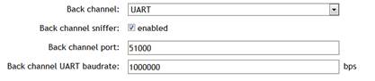
MIB2+
ICL uses UART of 1000000 bps.
The
communication data can be loaded from TCP port. The data formats are following:
12.1.1
Backchannel
UART
Here are
two UARTs captured uart0 and uart1.
Uart0 is
an output from MGB serializer (sent by display deserializer) and Uart1 is an
output from MGB deserializer (sent by ZR serializer).
UART TCP
channel sends 4 bytes at a time in the following bit-order
0 0 VC
VB VA UC UB UA | C C C C C C C C | B B B B B B B B | A A A A A A A A
Where
bit VC log 1 indicates that C byte is valid, UC log 1 indicates that C byte
holds uart1 byte and UC log 0 means it holds uart0 byte
Where
bit VB log 1 indicates that B byte is valid, UB log 1 indicates that B byte
holds uart1 byte and UB log 0 means it holds uart0 byte
Where
bit VA log 1 indicates that A byte is valid, UA log 1 indicates that A byte
holds uart1 byte and UA log 0 means it holds uart0 byte
E.g.: 0
0 0 1 1 0 1 0 | 0 0 0 0 0 0 0 0 | 0 0 0 0 1 1 1 1 | 1 0 1 0 1 0 1 0
means
only A byte and B byte are valid (C can be omitted) and A byte hold uart0 byte
0xAA and B byte hold uart1 byte 0x0F
This is
a way how to preserve UARTs byte orders with minimum overhead. Communication
must be parsed at TCP client side.
12.1.2
Backchannel
SPI
SPI
frames are also 4 bytes long, but only byte0 and byte1 are used. Other bytes
can be omitted.
D D D D
D D D D | C C C C C C C C | B B B B B B B B | A A A A A A A A
D byte
and C byte are omitted.
B byte
holds SPI data from MGB serializer (sent by display deserializer)
A byte
holds SPI data from MGB deserializer (sent by ZR serializer)
13
HDMI output
MGB has
HDMI output since MGB Board version 0.3. PCB version 0.3 is identified at web
interface (“Status/Board version”) or by presence of backlit On/Off switch
instead of separate LED on MGB box. HDMI output is enabled in “Video” menu at
web interface. When enabled, MGB negotiates attached monitor resolution and
streams out grabbed video which is resized to fit actual monitor screen. HDMI
output enabled can slow down MGB video Ethernet streaming or screenshot
performance because it runs on CPU instead of internal GPU, so if best
performance is necessary, HDMI output should be disabled. “HDMI output” option
is shown despite of MGB Board version, but is valid for version 0.3 and later
only (it does nothing at version 0.2).
14
Others
14.1
Logs
Since
firmware 1.3.1 has MGB internal logging mechanism that can help to find an
origin of a problem, freeze, etc…
User
just download logs from MGB and send them to E4T (Ondej.Hnilicka@e4t.cz) with a brief error description.
Logs are
accessible from web interface from “Other” menu (since v1.5.0) or at address http://<mgb-ip>/log.
Click to
all logs one after another, download generated files and send it us in email
attachment.
14.2
Date/Time
MGB has
internal Real Time Clock that is shown in HDMI output and can be set via web
interface. Please set your MGB’s clock at web interface “Other/Datetime” menu.
This helps with understanding of logs because these are synchronized according
to clock.
14.3
Serial
number
Serial
number functionality was implemented at firmware 1.3.1 and MGBs manufactured
prior this release were shipped with no serial number set. The serial number in
that case is “VX-SX-XX”. To
change serial number in MGB follow these steps:
·
Check
the serial number of your MGB. It is located inside the interface module drawer
after pulling the module outside (on yellow sticker).
·
Connect
to MGB’s console via UART terminal (connected to rear UART connector) or via
Putty at “MGB IP address” (specified in web interface).
·
Write
following commands: “root”, “cd MGB”, “./MGB_tools –serial <your_serial>”.
·
Serial
number is persistent and keeps the same after new firmware download
Note:
SWs before 1.6.7 had a bug which could rewrite the original serial number to
the default “VX-SX-XX” during upgrading to a new SW (less than 1.6.7). In such
cases, we recommend to flash SW 1.7.0 or later and fix the serial number by the
routine described above.
14.4
Configuration
reset
Since
firmware version 1.9 MGB has ability to reset its internal configuration to a
default values. It can be beneficial e.g. when a wrong settings of LAN address
obstructed an Ethernet connection and user cannot connect to web interface. In
such case follow the subsequent steps:
1)
Switch
OFF MGB
2)
Switch
ON MGB by On/Off button
3)
Wait
10 seconds (MGB is flashing green)
4)
Press
On/Off button and hold it pressed until MGB light become yellow. Release On/Off
button.
5)
Wait
30 seconds, then switch MGB OFF by On/Off button
6)
Switch
ON MGB…now the configuration is reset to defaults